
Control Widget - SCADA
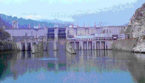
In the process of the realization of remote surveillance and control system of H.E. Višegrad (Republic of Srpska, hydro power plant 315 MW installed power) we used the Control Widget software package applied on IBM PC equipment and Allan Bradley Open Controller. The system, which is in exploitation for more than two years , has the following basic functions:
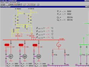
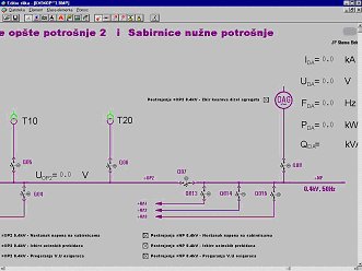
- Graphical presentation and status monitoring of the power circuit schemas
- The notes on alarm, malfunction and other system events.
- Chronological registration of events by 10ms resolution
- Archiving of all system measurements
- Reports:
- Power-plant report (production threshold, generators, active, reactive and self power consumption, balance, average hour power consumption, aggregate status, voltage status,...))
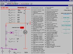
- Electric maintenance report (monitoring of transformer parameters, firework devices, pneumatic subsystem, deep droppers, iridescence, entering facility, DV fields status, tunnel gas zone...)
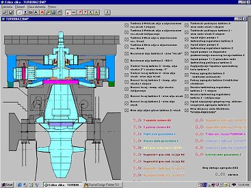
- Machine reports (monitoring of chilling water in filter station, brakes air pressure, regulation field devices, generator temperature, vibrations...)
System description
"CONTROL WIDGET" is a descendant of VIEW6000 SCADA software package, previously designed by "Mihajlo Pupin" Institute. It has specially added functionality for the controll and surveillance of the hydro power plant. It is implemented in the versions for IBM RISC6000 family as well as for IBM PC compatible computers running on UNIX base operating systems (AIX, LINUX, etc.). It could be used for electric power facilities of small and medium complexity, as well as for large regional surveillance and control systems (such as electric power distribution systems, pipeline networks etc.) The intention of this document is to get the potential user familiarized with all of the important features and possibilities of this product.
"CONTROL WIDGET" is distributed surveillance/control system realized in client/server architecture with one or more end stations (RTU - Remote Terminal Units). The technical solution of CONTROL WIDGET system has the following features:
- Use of the base technology consisting of the highly standardized components complied to POSIX (IEEE1003.1) UNIX , X Windows, R11 distributed graphical system, OSF /MOTIF 1.2.4 based MMI (Man Machine Interface) implemented due to Motif Style Guide, SQL interface to the technical database, TCP/IP based LAN/WAN
- Implementation of so called OPEN technologies that enable interconnectivity of hardware/software products of different vendors
- Use of the technology which enables database transparency to the different hardware platforms of the different artchitectures/vendors
- The system is distributed, which means that the necessary resources could be dimensioned in flexible manner, could be easily enlarged, it's components could be located on the different network nodes, could connect to any other system which is complied to the above mentioned standards.
- Implemented in full graphics, in windowing environment, using MDI (multi document interface)
- Converts image files of all well known graphical formats to it's internal format.
- Transparent to PC/MSDOS/Windows LAN nodes, which includes file transfer, X-Windows emulation (with copying to/from an X window), remote procedure calls etc.
CONTROL WIDGET System Configuration
The basic configuration consists of the following components:
a) RTU (Remote Terminal Unit)
b) CONTROL WIDGET server (CW server)
c) CONTROL WIDGET workstation (CW workstation)
All computers are connected through LAN realized on Ethernet link. The network communication protocol is TCP/IP. The RTU, situated on the location of the specific object, collect the incoming signals and updates the local database. It also runs the user programs that are loaded from the programming terminal. RTU communicates with CW server as a slave-type device.
The connection between RTU and CW server is usually the serial asynchronous link with an optional modem interface. The other types of connections are also possible.CW server centralizes the real-time database, updates it through communication with RTU's, makes the archive files on local disk, and offers the necessary services to the CW workstation computers. There could be more than one CW workstation computers in the system. They usually run MMI software package and X11 R6 server. User interface is implemented in X11/Motif environment and presents the events collected from the system through the shape of dynamical images, lists, tables, trend diagrams and reports. The user is also allowed to issue the command requests to the system through the collection of user-friendly dialog forms, to start the archiving process in order to generate the necessary output needed for the post-mortem analysis etc. The existing user computers could also be connected on LAN.
One of them gets the role of engineer station. Optionally one of them could be used to have installed the dual boot program in order to start in DOS/WINDOWS mode. This computer is usually used for the installation of the off-line programs that are used for the creation and maintenance of the dynamic images and configuration of the real-time database. After the export of data to the CW server is made, this computer could be used for the purposes that are not necessarily connected with the work of the SCADA system.The WAN connection is implemented on CW server. The network uses the asynchronous serial link with the modem interface and is of the point-to-point type. The printing devices that could be connected to CW server are:
- Logger Printer - spontaneous printing of the event log
- Printer for the periodical issuing of the reports
The printer, which is connected with the CW server, is intended for local graphical printing.
Motivation
The basic function of the system is the process visualization, report generation and remote control of the process. It also includes the daily, monthly and annual monitoring of the hydro power plant activity and electrical and machine equipment status in the following fields of interest:
- Power plant activity monitoring functions
- Monitoring of the 15 kV and 400 kV status
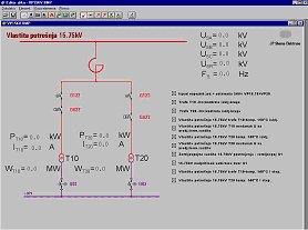
- Power self-consumption
- Monitoring of the planned production - planned/realized
- Total daily report of the power plant
- Manual entry of the weather forecast
Electrical equipment monitoring
- Deep droppers (oil level, signalization status)
- Command racks of voltage generator switches (air pressure)
- Overflows (oil level, working of the heaters, signalization)
- Working of switch compressor (pressure, hours of work)
- Temperature of transformer oil.
- Entering facilities (closers, oil level, signalization).
- Firework equipment.
- Transformers.
Machine equipment monitoring
- Monitoring of the generator activity
- Pressure of the chilling water in the filter station
- Breaking air pressure
- Regulation field devices